Learn Basics of CAD Modelling & Animation, CAD Assembly Design, Advance CAD, Basic Introduction on FEA, ANSYS Workbe nch GUI and Meshing, Static and Dynamic structural analysis accompanied with various recent case studies to attain the challenges set by the EV industries with Personalized Industry Mentorship, Career Guidance, and Placement Assistance and much more.
SolidWorks & Ansys
Learn Basics of CAD Modelling & Animation, CAD Assembly Design, Advance CAD, Basic Introduction on FEA, ANSYS Workbe nch GUI ...
Show more
- Description
- Curriculum
- Reviews
About the Program

Personalised Mentorship
Get mentored by an experienced EV Industry expert and receive personalised feedback calls for better career guidance.

Globally Valid Certificate
Get a Globally valid certificate and enter your workplace with confidence and assert yourself as a subject matter expert.

Student Support
Student support available 09 AM to 07 PM IST via email or call and get a response within 2 working hours.

Level 1 Certification
In SolidWorks & Ansys
Complete all the courses successfully to obtain the certification
• Globally Recognized Certificate
• Recommended program by SMEV, MSME and 17 + Automotive Industries.

Still Not sure?
Talk to our Expert Mentors
An Expert will reach out to you within 6 Hours
About SolidWorks & Ansys Program
SOLIDWORKS is a software tool that is used right from the conceptualization of the design until the final manufacturing of the product. As the world’s leading tool in designing, it supports interactive learning of 3D modelling. The implementation of such software can lend several benefits to the users, such as:
● Shortened Design Cycle
● Increased Productivity of Engineers and Designer
● Faster Deliver Innovative Products
The Ansys finite element solvers enable a breadth and depth of capabilities unmatched by anyone in the world of computer-aided simulation. Thermal, Structural, Acoustic, Piezoelectric, Electrostatic and Circuit Coupled Electromagnetic are just an example of what can be simulated. Regardless of the type of simulation, each model is represented by a powerful scripting language … the Ansys Parametric Design Language (APDL). APDL is the foundation for all sophisticated features, many of which are not exposed in the Workbench Mechanical user interface. It also offers many conveniences such as parameterization, macros, branching and looping, and complex math operations. All these benefits are accessible within the Ansys Mechanical APDL user interface.
This course introduces new users, or experienced Ansys Mechanical users, to the Ansys Mechanical APDL user interface. The Mechanical APDL workflow, graphical user interface, and APDL command syntax will be introduced. With this foundation in place, users can apply this knowledge to efficiently set up, solve, and post-process virtually any type of analysis.
Course Objectives
The course aims to give students and professionals the essentials that are needed to become a certified SOLIDWORKS & ANSYS associate. The course will help individuals use the software with confidence and design/draft the next innovative thing.
SOLIDWORKS is used internationally by millions of companies
● The software grants the designer, ability to import data, store it securely while maintaining flexibility and accessibility
● Designers and engineers categorize SOLIDWORKS as an innovative way to accept project challenges
After completing this course, You will Comfortably navigate the Mechanical user interface and apply a proven workflow for creating, solving, and post-processing 2-D and 3-D finite element models.
Eligibility
-
Program designed for Professionals / Academicians / Engineers / Undergraduate Students and all interested Electric Vehicle enthusiasts
Recorded Videos, Case Study and Assessment
-
Online program which is time-independent, meaning that it can be accessed 24 X 7 lifetime. Case Study and Assessment by Experts after completion of each unit. This program is available Online on ISIEINDIA E-Learning APP and Website.
Free Research Paper Publication
-
Case Study on Live model, Research Paper Writing and Free Research Paper Publication. Downloadable kit includes tools such as e-books, research paper references and gazetted government reports are made available at just one click.
Feedback & Interaction
-
Practical hands-on activities and video Lectures with interactive portal/forum for discussion among students. Prompt feedback to every slight curiosity and query by instructor/trainer are part of this course.
Program Outcomes

Static and Dynamic structural Analysis
CAD Library – To turn up productivity by using CAD library.
Costing – To check the value of design against manufacturing cost.
CAD Modelling and Animation – To develop 3D, animated movie of product design.
Weldment Design – To model welded structures with standard structural members.
Use Selection Logic to efficiently operate on sub-regions of a model for meshing, loading, and post-processing.
Tolerance Analysis - To analyze the tolerance level of each part individually and of parts when functioning collectively.
Assembly Design – To design parts and assemble them.
Introduction on FEA, ANSYS Workbench GUI and Meshing.
Product Data Management – To repurpose design data in a safe manner.
Sheet Metal Design – To design parts which are to be fabricated with sheet metal.
Import and/or create geometry as needed for the creation of their simulation model.
Build complex interactions among model regions through contact, coupling, constraint equations, and bolt/gasket interfaces.
Understand the concept of element attributes and apply it to building effective, efficient meshes using beam, shell, and solid elements.
ISIEINDIA Instructors
Learn from leading Industry oriented trainer, faculty and leaders


Our Expert Work At
Top companies from all around the world


ISIEINDIA Alumni
Where our Alumni Work
Payment Offers
Now, pay your course fees in installments at no cost EMI available at Credit cards following banks
Basics of CAD Modelling & Animation
CAD Assembly Design
-
1
 Basics of Assembly design
 -
2
Design of Parts and Assembly
-
3
Wheel Assembly M- 1+M-2+M-3
-
4
Mini Project on Product Design and Assembly
-
5
Electronic cabinet assembly
-
6
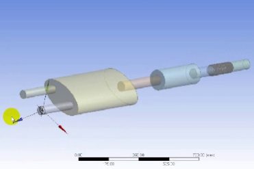
 Project: CAD Modelling1) Download the attached document and proceed with the solution. 2) Solution has to be submitted in same format as that of attached document. 3) Images for the simulation part has to be contained with this document only.
Advance CAD Part - 2
Advance CAD Part -1
ANSYS Workbe nch GUI and Meshing
Basic Introduction on FEA
Static and Dynamic structural analysis
Please, login to leave a review
Course details
Duration
1 Month
Lectures
29
Video
15+ Hours
Level
Beginner
Popular courses